


 English
 русский
 Español
 عربى


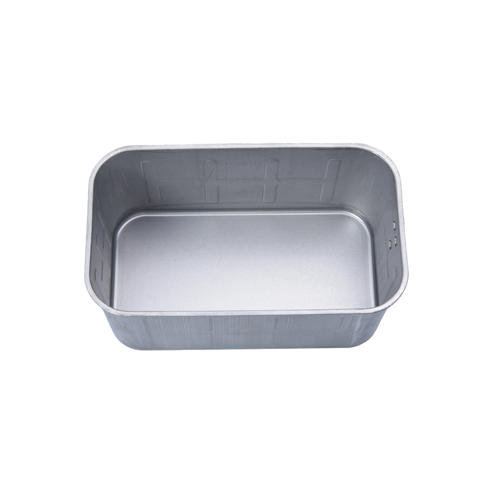
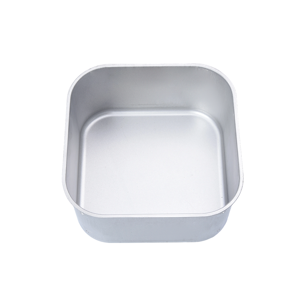
When you need a metal component whose depth clearly exceeds its width, such as a one-piece battery enclosure, an air-fryer inner container,...
READ MORE

News
Home / Author / Liu Yanan — Product After-Sales Service Specialist / Deep-Drawn Containers with Cutouts for Precision Industrial Applications
Deep-Drawn Containers with Cutouts for Precision Industrial Applications
2026-09-06
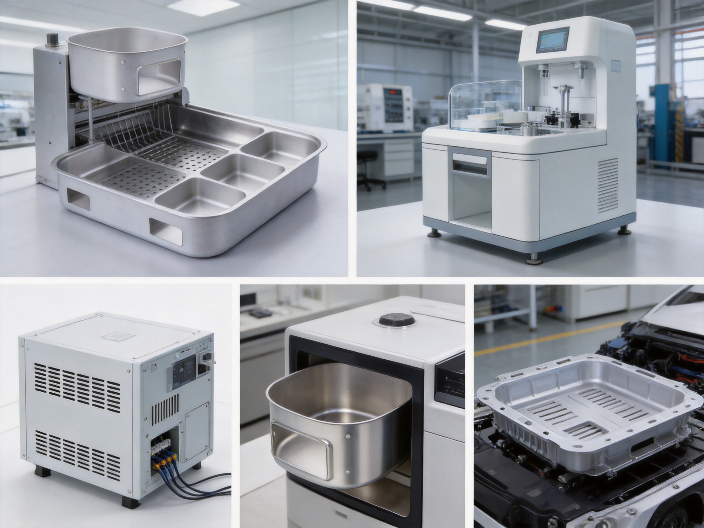
Deep-drawn containers with cutouts are engineered metal components designed for applications that require strength, dimensional consistency, cleanliness, and reliable integration with surrounding assemblies. By combining deep-drawing technology with accurately formed openings, slots, vents, and drainage features, these containers provide a practical alternative to multi-piece fabricated enclosures, welded vessels, and less precise formed components.
The product is suitable for industrial equipment, food-processing machinery, medical devices, electronics, household appliances, automotive systems, and mechanical assemblies. Its one-piece construction supports a clean appearance and dependable service life, while its customizable geometry allows the container to be adapted to specific installation, ventilation, drainage, wiring, access, and assembly requirements.
Yuyao Hongli Optoelectronics Co., Ltd. manufactures deep-drawn parts, stamped parts, bending parts, kitchen appliance accessories, and automotive stamping parts for customers requiring consistent production and flexible OEM/ODM support. With more than 20 years of industry experience, a modern factory, multiple stamping workshops, and an experienced production team, the company is positioned to support projects ranging from prototypes and small batches to repeat large-volume orders.
What Is a Deep-Drawn Container with Cutouts?
A deep-drawn container is produced by forcing a flat sheet of metal into a shaped die with a forming punch. Instead of assembling several flat panels and joining them together, the manufacturing process gradually transforms the sheet into a three-dimensional container. The result can include a base, side walls, corners, flanges, stepped areas, and other formed characteristics within a unified component.
Cutouts are openings intentionally incorporated into the component. Depending on the application, they may function as ventilation openings, drainage holes, cable passages, inspection windows, mounting slots, fastening points, or access features. Their size, shape, position, quantity, and edge treatment can be developed according to the requirements of the final assembly.
The combination of deep drawing and cutout production offers important design flexibility. A customer may require a compact container with a set of holes for wiring, a tray with drainage openings, a medical equipment housing with controlled access slots, or an appliance component with formed edges and mounting points. Rather than adapting a standard product to an unsuitable application, the design can be engineered around the intended operating environment.
Because the main body is formed from a single piece of sheet material, the container can reduce the number of joints, seams, and separate parts in an assembly. This may simplify downstream installation, reduce handling time, and create a more uniform appearance. It can also help designers address cleanliness requirements in environments where dirt, liquid, or processing residue must not accumulate around unnecessary joints.
Core Product Characteristics
The deep-drawn container with cutouts is designed to provide a combination of mechanical performance, manufacturability, and customization. The exact dimensions and specifications are developed according to the customer’s drawings, samples, application conditions, and production requirements.
One-Piece Formed Construction
The container is formed through a deep-drawing process that creates a seamless main body without relying on conventional welding of multiple panels. This construction approach can deliver a smooth and continuous surface across the base and walls. It also eliminates many of the potential inconsistencies associated with manually assembled corners or welded joints.
A one-piece structure is particularly valuable for containers used in wet, dusty, hygienic, or chemically demanding environments. Fewer seams can make the component easier to clean and may reduce locations where moisture or residue can collect. In addition, the absence of visible weld lines on the primary formed body can support a more consistent appearance in finished equipment.
Custom Cutouts and Openings
Cutouts can be designed to support the exact function of the component. Vent openings may help promote airflow around heat-generating equipment. Drainage holes may allow liquid to leave the container rather than remain in the bottom. Wiring slots can provide controlled cable routing, while mounting holes and fastening openings can simplify installation.
Cutout features can be positioned on the base, side walls, end walls, flanges, or other accessible areas of the container. Their geometry may be round, rectangular, elongated, irregular, or designed around a particular connector or fastening system. When necessary, edge conditions can be reviewed to improve safety, appearance, fit, and resistance to deformation during use.
Material Thickness Options
The available thickness range is approximately 0.5 to 3.0 millimeters, subject to the selected material, component geometry, forming depth, and production requirements. A thinner sheet may support weight reduction and efficient material use, while a thicker sheet may be selected when greater rigidity, impact resistance, or load-bearing capability is required.
Thickness selection should be based on more than nominal dimensions. The design team must consider draw depth, corner radii, wall stability, cutout size, flange width, handling conditions, fastening loads, and the possibility of material thinning during forming. Hongli can review these factors during the quotation and engineering stages to help match the design with a practical manufacturing solution.
Surface Finish Choices
Several surface finish options are available, including brushed, polished, sandblasted, and electropolished finishes. Each finish creates a different combination of appearance, texture, reflectivity, cleanability, and application suitability.
A brushed finish provides a directional appearance and can help create a practical surface for equipment panels and visible appliance components. A polished finish offers a smoother and more reflective appearance where presentation and easy wiping are important. Sandblasting creates a controlled matte texture, while electropolishing can provide a smooth, clean surface suitable for applications that place a high value on hygiene and surface quality.
The final finish should be selected according to the operating environment and the customer’s expectations. A finish used for a food-processing component may have different priorities from one used for an automotive bracket or an internal electronic enclosure. Surface treatment, packaging, and handling procedures can be coordinated to protect the finished part before it reaches the customer’s assembly line.
Durability and Corrosion Resistance
The product is intended for demanding service conditions in which durability, impact resistance, and corrosion resistance are important. The formed construction helps create a robust component with fewer assembled joints. The appropriate material and surface finish can further support resistance to moisture, routine handling, cleaning operations, and general industrial exposure.
Performance depends on the material grade, thickness, geometry, environmental conditions, and finishing method selected for the project. For this reason, application details should be reviewed before production. Factors such as temperature, contact with food or cleaning agents, exposure to chemicals, outdoor use, vibration, and repeated mechanical loading may affect the recommended specification.
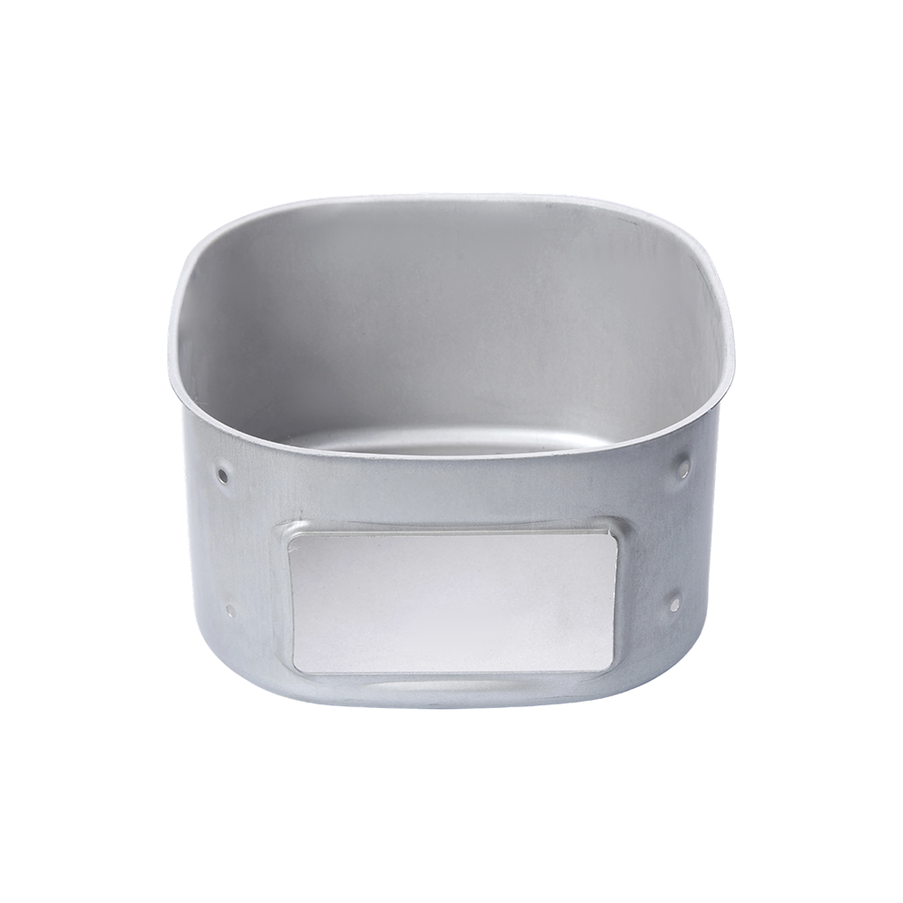
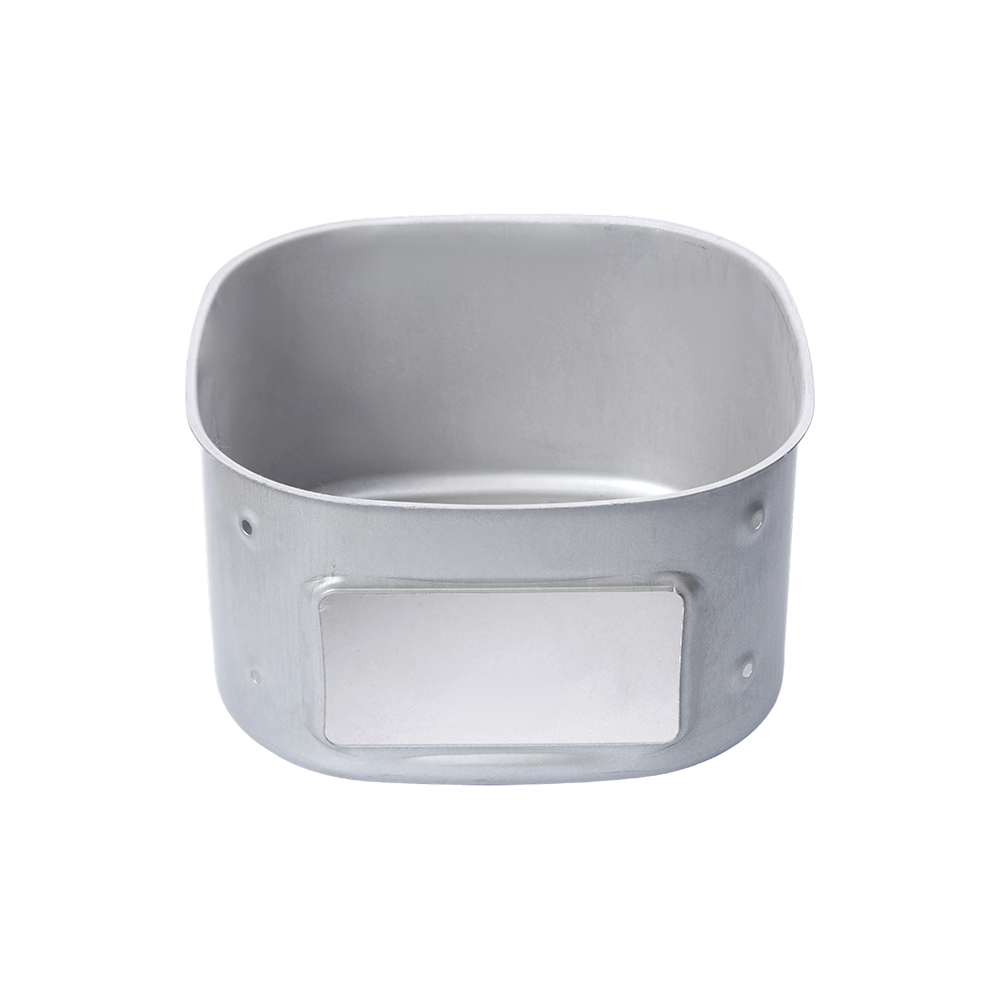
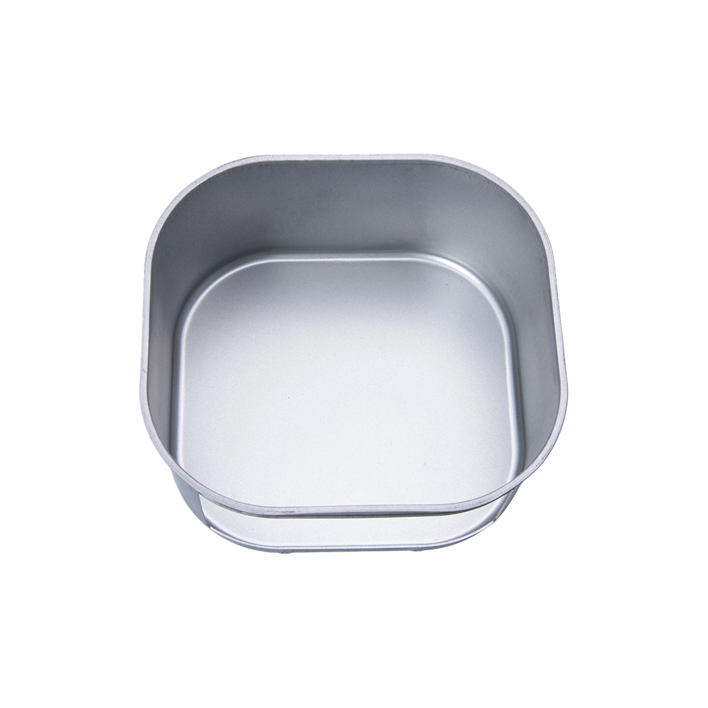
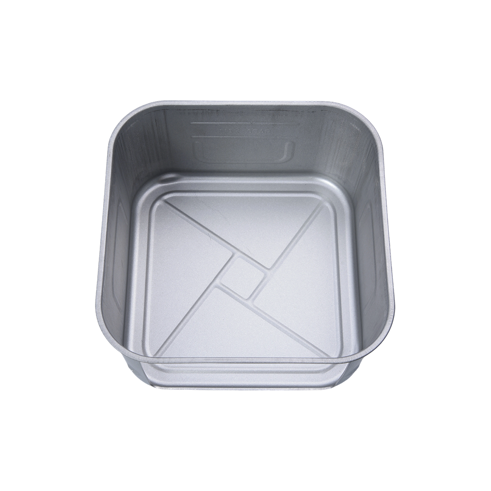
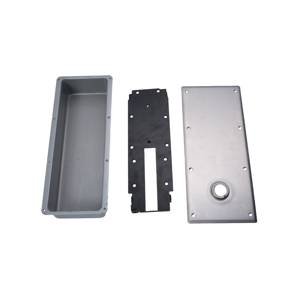
Deep-drawn container with cutouts
Advantages Compared with Conventional Fabricated Containers
Deep-drawn containers compete with welded sheet-metal boxes, bent-and-assembled trays, plastic housings, and standard containers that offer limited customization. The most suitable solution depends on the application, but deep drawing provides several distinct advantages when the component requires a formed, strong, and clean one-piece structure.
Reduced Dependence on Welding
Conventional containers may be made by cutting several panels, bending each panel, aligning the pieces, and welding them together. This method can be effective for certain low-volume or highly complex products, but it introduces additional operations and potential variation. Welding may create heat-affected areas, visible seams, distortion, spatter, or post-processing requirements.
A deep-drawn container forms the primary body in one continuous operation or a sequence of controlled drawing operations. By reducing the number of welded joints, the product can provide a more uniform appearance and a simpler surface for cleaning. The manufacturing route may also reduce the need for grinding, seam treatment, and other secondary corrections associated with multi-piece fabrication.
Improved Structural Continuity
Deep drawing creates continuous walls between the base and the sides of the container. This structural continuity can improve rigidity and reduce the number of weak points caused by separate panels and joints. Rounded corners and controlled transitions may also distribute stress more smoothly than sharp assembled intersections.
The final structural performance depends on the geometry and material, but the one-piece design is often advantageous when the product must withstand handling, vibration, moderate impact, or repeated installation. For equipment manufacturers, a stronger formed component can support a longer service life and help protect the components housed inside the container.
Efficient and Repeatable Production
Once the forming dies and process parameters have been established, deep drawing can support efficient repeat production. The use of dedicated tooling helps maintain consistent dimensions from one part to the next. This is important for customers who need components to fit the same equipment model over multiple production cycles.
Repeatability can reduce the time spent adjusting parts during assembly. It may also help simplify inventory planning, quality inspection, and replacement-part management. For larger orders, the productivity of a controlled stamping and drawing process can provide a cost advantage compared with labor-intensive individual fabrication.
Better Adaptation to Clean and Hygienic Applications
Containers used in food-processing, medical, laboratory, and clean equipment environments often require surfaces that are easy to inspect and maintain. A seamless or low-seam structure can help limit areas where residue may accumulate. Smooth finishes and carefully designed cutout edges can further support cleaning and maintenance procedures.
Although the complete hygiene performance of a component depends on the material, finish, cleaning method, and system design, the deep-drawn format offers a strong foundation for applications where cleanability is a priority. The design can be reviewed to avoid unnecessary pockets, inaccessible recesses, and difficult-to-clean joints.
Lightweight Strength
Deep-drawn sheet-metal components can provide a useful balance between low weight and mechanical strength. Rather than using a solid block or an unnecessarily heavy assembly, the container uses formed walls to create rigidity with relatively efficient material usage. This can be valuable in automotive, appliance, portable equipment, and electronics applications where every gram may influence handling or system weight.
Lightweight design does not mean sacrificing functionality. Wall depth, flange geometry, formed ribs, corner design, and material thickness can be evaluated together to achieve the required balance of weight, stiffness, and durability.
Flexible Customization
Standard containers may require compromises in dimensions, access, drainage, or mounting. A custom deep-drawn container allows the component to be developed around the customer’s actual assembly. This can reduce the need for adapters, additional brackets, manual modifications, or post-production drilling.
Customization may include overall length, width, height, draw depth, wall thickness, corner radius, flange size, cutout design, mounting features, surface finish, packaging, and production quantity. The ability to combine several requirements in one engineered component is one of the main reasons customers choose a custom stamping supplier.
Manufacturing Process
Reliable deep-drawn products depend on more than a stamping press. They require coordinated engineering, material preparation, tooling, forming, cutout production, finishing, inspection, and packaging. A disciplined process helps transform the customer’s concept into a component that is practical to manufacture and consistent in service.
1. Drawing and Requirement Review
The process begins with a review of the customer’s drawings, three-dimensional files, samples, specifications, and intended use. Important information includes the material, thickness, overall dimensions, draw depth, cutout locations, tolerances, surface requirements, expected quantity, and delivery schedule.
The application review is equally important. A container intended for a food-processing machine may require a different finish and cleaning approach from an automotive stamping component. A part exposed to vibration may require attention to mounting strength, while a small electronic enclosure may prioritize compact dimensions and cable access.
2. Design for Deep Drawing
Deep drawing is most successful when the product design accounts for the behavior of sheet material during forming. The engineering team evaluates draw ratios, corner radii, material flow, flange dimensions, wall transitions, and the sequence of forming operations. These decisions influence the risk of wrinkling, tearing, excessive thinning, distortion, and dimensional variation.
Cutouts also require careful planning. Openings created before forming may change shape during the drawing operation, while openings created after forming may require a separate punching, laser, or machining step. The most appropriate sequence depends on the location and geometry of the feature. By considering cutouts during the initial design stage, the manufacturer can reduce rework and improve positional accuracy.
3. Tooling and Die Development
Deep-drawing dies control the movement of the sheet during forming. Tooling may include a die, punch, blank holder, guide components, trimming features, and additional stations for secondary operations. The tool design must provide sufficient support while allowing the material to flow into the desired shape.
For products with significant depth or complex geometry, multiple drawing stages may be used. The part can be gradually formed through controlled operations rather than being forced into its final shape in one step. This approach can improve stability and reduce stress on both the material and the tooling.
Tooling selection is influenced by projected production volume. A prototype or small batch may use a flexible and economical tooling approach, while a high-volume program may justify dedicated progressive or multi-operation tooling. Hongli can discuss tooling and production strategies according to the customer’s expected order pattern.
4. Material Preparation
Sheet material is prepared according to the approved specification. The material must be suitable for the required forming depth and final application. Coil or sheet preparation may include cutting blanks to the appropriate dimensions and inspecting the material for visible defects or inconsistencies.
Blank size is an important process variable. An undersized blank may not provide enough material for the required walls and flange, while an oversized blank may increase waste or complicate material flow. Accurate blank preparation supports stable forming and efficient material use.
5. Deep-Drawing Operation
During deep drawing, the blank is placed over the die and held under controlled pressure while the punch moves the material into the cavity. The blank holder helps manage material flow and can reduce wrinkling. The pressure, speed, lubrication, clearance, and tool condition must be controlled to protect the surface and maintain the intended geometry.
Depending on the design, the container may pass through one or more drawing stages. Intermediate forming can gradually increase the depth while preserving wall integrity. Process parameters are adjusted according to the material, thickness, shape, and required dimensional accuracy.
A well-controlled drawing operation produces consistent walls and smooth transitions. It also establishes the foundation for later cutout, trimming, finishing, and inspection operations. Poorly controlled forming can lead to tearing, wrinkles, uneven walls, or distortion, which is why experienced process management is essential.
6. Trimming and Edge Formation
After drawing, excess material may be trimmed to create the final outline or flange. Trimming can be performed through stamping or another suitable cutting operation. The finished edge should be reviewed for dimensional accuracy, burrs, sharp corners, and compatibility with the customer’s assembly.
Where necessary, additional forming may create rolled edges, mounting flanges, stiffening sections, or other functional details. These features can improve handling safety, increase rigidity, or provide a defined interface with neighboring parts.
7. Cutout Production
Cutouts may be formed through punching, stamping, laser cutting, machining, or a combined process. The best method depends on the material, thickness, opening geometry, quantity, tolerance, and position of the feature.
Punching is efficient for repeated holes and slots, particularly in larger production runs. Laser cutting can provide flexibility for changing patterns, prototypes, and complex profiles. Machining may be selected when a feature requires special accuracy or when the component geometry makes another method impractical.
Cutout production is controlled to maintain the specified location and size. The edges are checked for burrs and deformation, especially when the openings will be used for wiring, assembly, fluid drainage, or contact with other components. Edge quality is important for both safety and performance.
8. Surface Finishing
After forming and cutting, the container receives the specified surface treatment. Brushing, polishing, sandblasting, and electropolishing are available according to the project requirements. Finishing may improve appearance, cleanability, tactile quality, or resistance to the intended environment.
Before finishing, the part may undergo cleaning, deburring, and visual preparation. These steps help remove process residue and improve the uniformity of the final surface. The finishing method must be compatible with the material and should not compromise critical dimensions or cutout edges.
9. Inspection and Quality Control
Quality control may include material verification, visual inspection, dimensional measurement, cutout inspection, surface review, and functional fit checks. The inspection plan is determined by the product requirements and the customer’s quality expectations.
Key dimensions may include overall length, width, height, draw depth, wall position, flange dimensions, corner radii, hole diameter, slot length, and cutout location. For repeat orders, process records and inspection results can help identify trends and support consistent production.
Quality control is most effective when it begins during design and tooling rather than only after production. Early review of manufacturability, process capability, and inspection requirements helps prevent avoidable problems and supports more stable delivery.
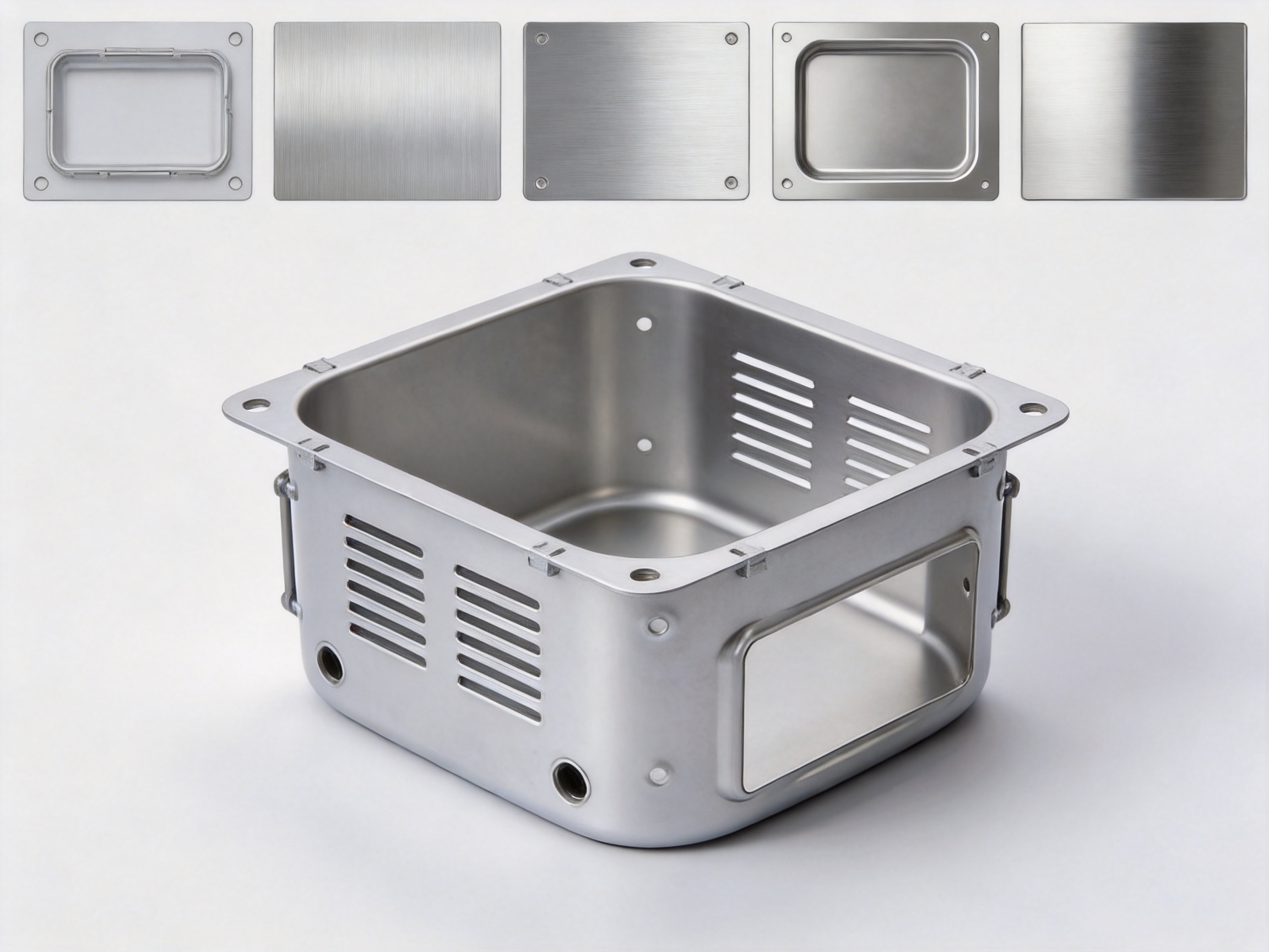
Applications Across Multiple Industries
Food-Processing Equipment
Food-processing machinery often requires components that can be cleaned efficiently and withstand regular handling. Deep-drawn containers may be used as trays, covers, collection vessels, equipment inserts, or protective housings. Drainage cutouts can help remove liquid, while smooth finishes can support routine cleaning.
The final material, finish, and geometry should be selected according to the food-processing environment and the customer’s applicable requirements. Openings and corners can be designed to reduce residue accumulation and improve access during maintenance.
Medical and Laboratory Equipment
Medical and laboratory equipment frequently includes compact metal housings, trays, covers, brackets, and internal containers. These components may need a clean appearance, accurate dimensions, corrosion resistance, and surfaces that can be wiped or disinfected as appropriate for the equipment design.
Custom cutouts can accommodate cables, connectors, ventilation, switches, sensors, or mounting hardware. A one-piece formed component can reduce the number of seams and simplify integration into a larger device.
Electronics and Electrical Equipment
Electronic systems often require lightweight enclosures and internal metal parts that provide protection while allowing airflow and cable routing. Deep-drawn containers can include ventilation openings, connector passages, fastening holes, and formed mounting features.
The container’s geometry can be adapted to circuit boards, power supplies, sensors, batteries, or other internal components. Cutout placement can be coordinated with assembly access and service requirements, helping equipment manufacturers avoid additional brackets and manual modifications.
Household Appliances
Household appliances may use deep-drawn components in heating equipment, kitchen appliances, small electrical products, protective covers, internal trays, and structural supports. The combination of formed strength and surface finish options allows the part to serve either a visible or concealed function.
Kitchen appliance accessories can benefit from smooth, easy-to-maintain surfaces and a design that avoids unnecessary seams. The component can also be developed with mounting holes, ventilation slots, drainage openings, or interface flanges that match the appliance assembly.
Automotive Systems
Automotive stamping parts must meet demanding expectations for consistency, fit, durability, and production efficiency. Deep-drawn containers and related formed components may be used in brackets, protective covers, housings, trays, structural inserts, and other vehicle systems.
Automotive applications often require repeatability across substantial production quantities. Stable tooling, controlled stamping operations, accurate cutouts, and effective inspection are important to ensure that each part can be installed efficiently on the production line.
General Mechanical Equipment
Mechanical equipment manufacturers may require custom containers for lubricant collection, component protection, access covers, machine interiors, cable management, or equipment frames. The dimensions and openings can be developed around the machine architecture, allowing the formed part to function as both a container and an integrated structural element.
Product Specification Overview
| Item | Available or Customizable Specification | Application Benefit |
|---|---|---|
| Product type | Deep-drawn metal container with cutouts | One-piece formed structure with integrated openings |
| Material thickness | Approximately 0.5 to 3.0 mm, subject to design review | Supports different weight, rigidity, and forming requirements |
| Cutout features | Vents, drainage holes, slots, mounting holes, wiring passages, and custom profiles | Improves airflow, drainage, installation, and system integration |
| Surface finishes | Brushed, polished, sandblasted, or electropolished | Supports appearance, cleanability, texture, and application needs |
| Manufacturing method | Deep drawing with trimming, cutout production, forming, and finishing operations | Provides repeatable production and reduced assembly complexity |
| Customization | Dimensions, geometry, openings, thickness, finish, and packaging | Allows the part to match specific equipment and production requirements |
| Order support | Prototype, small-batch, and larger-volume production | Provides flexibility throughout product development and commercialization |
Engineering Benefits for Product Designers
When designers choose a custom deep-drawn container, they can address several system-level requirements within a single component. Instead of specifying a standard box plus separately attached brackets, covers, and cable plates, the design may incorporate these functions into the formed metal body.
This integration can reduce the total part count and make the assembly easier to understand. Fewer individual parts may also mean fewer fasteners, lower handling requirements, and fewer opportunities for assembly errors. In some applications, the container can act as a protective housing, mounting platform, drainage tray, and airflow component at the same time.
Designers should provide complete information about the intended use, including load conditions, environmental exposure, cleaning requirements, temperature range, installation method, and expected production quantity. This information allows the manufacturing team to recommend practical wall thicknesses, corner radii, cutout methods, and finishing options.
It is also beneficial to involve the manufacturer before the design is finalized. Early design-for-manufacturing review can identify areas where a small geometry change may improve material flow, reduce tooling complexity, shorten production time, or improve dimensional stability. Such cooperation can reduce the risk of expensive changes after tooling has begun.
Why Choose an Experienced Stamping Manufacturer?
Deep drawing is a specialized forming process. A supplier may have the equipment to press sheet metal but still lack the engineering experience required to produce a stable, high-quality deep-drawn component. An experienced manufacturer understands how material behavior, tooling, press conditions, secondary operations, and inspection requirements interact.
Yuyao Hongli Optoelectronics Co., Ltd. has more than 20 years of experience in metal stamping and related manufacturing. The company was founded in 2000 and has developed from its earlier business identity into a professional manufacturer serving customers across several product categories.
The company operates a modern factory of approximately 5,000 square meters and has multiple stamping workshops. With more than 60 employees, Hongli supports production activities involving educational instruments, optical instruments, household electric heaters, small household appliances, automotive parts, hardware products, plastic products, deep-drawn parts, stamped parts, bending parts, kitchen appliance accessories, and automotive stamping parts.
This broad experience is valuable because many customer projects combine several manufacturing requirements. A deep-drawn container may need additional bending, punching, trimming, fastening features, or related stamped components. A supplier familiar with multiple metal-forming processes can coordinate these requirements more effectively than a supplier limited to one operation.
OEM and ODM Support
Hongli provides OEM and ODM customization for customers who need products developed from drawings, samples, concepts, or existing components. The company can participate in design communication, process review, prototyping, tooling coordination, production, inspection, and delivery planning.
OEM support is useful when the customer already has a completed design and requires a reliable manufacturing partner. ODM support is useful when the customer has a functional requirement but needs assistance converting that requirement into a production-ready component.
Rapid Prototyping and Production Conversion
Product development often begins with a prototype or small trial order. At this stage, the priority may be confirming fit, finish, cutout placement, installation, and function before committing to a larger production program. Hongli supports rapid prototyping and efficient production conversion, helping customers move from development to repeat manufacturing.
The transition from prototype to production should be managed carefully. The prototype process may use flexible methods, while high-volume production may require dedicated stamping tools. Dimensional relationships, material behavior, finishing requirements, and inspection criteria should remain consistent as the process changes.
Quality and Delivery Focus
Stable quality and dependable delivery are important to equipment manufacturers because a missing or inconsistent component can interrupt assembly. Hongli emphasizes strict quality control, stable delivery, and comprehensive after-sales service as part of its customer support approach.
Production planning includes consideration of raw materials, tooling, press capacity, secondary operations, surface finishing, inspection, and packaging. Coordinating these stages helps reduce delays and ensures that finished products are prepared according to the customer’s requirements.
Flexible Order Quantities
Not every customer requires the same production volume. Some need a small batch for testing, while others require regular supply for established equipment programs. A flexible manufacturing partner can adapt the production approach to the order size while maintaining attention to quality and delivery.
Customers are encouraged to discuss forecast quantities, target annual demand, initial order size, and expected repeat frequency. This information can guide decisions about tooling investment, production scheduling, packaging, and cost optimization.
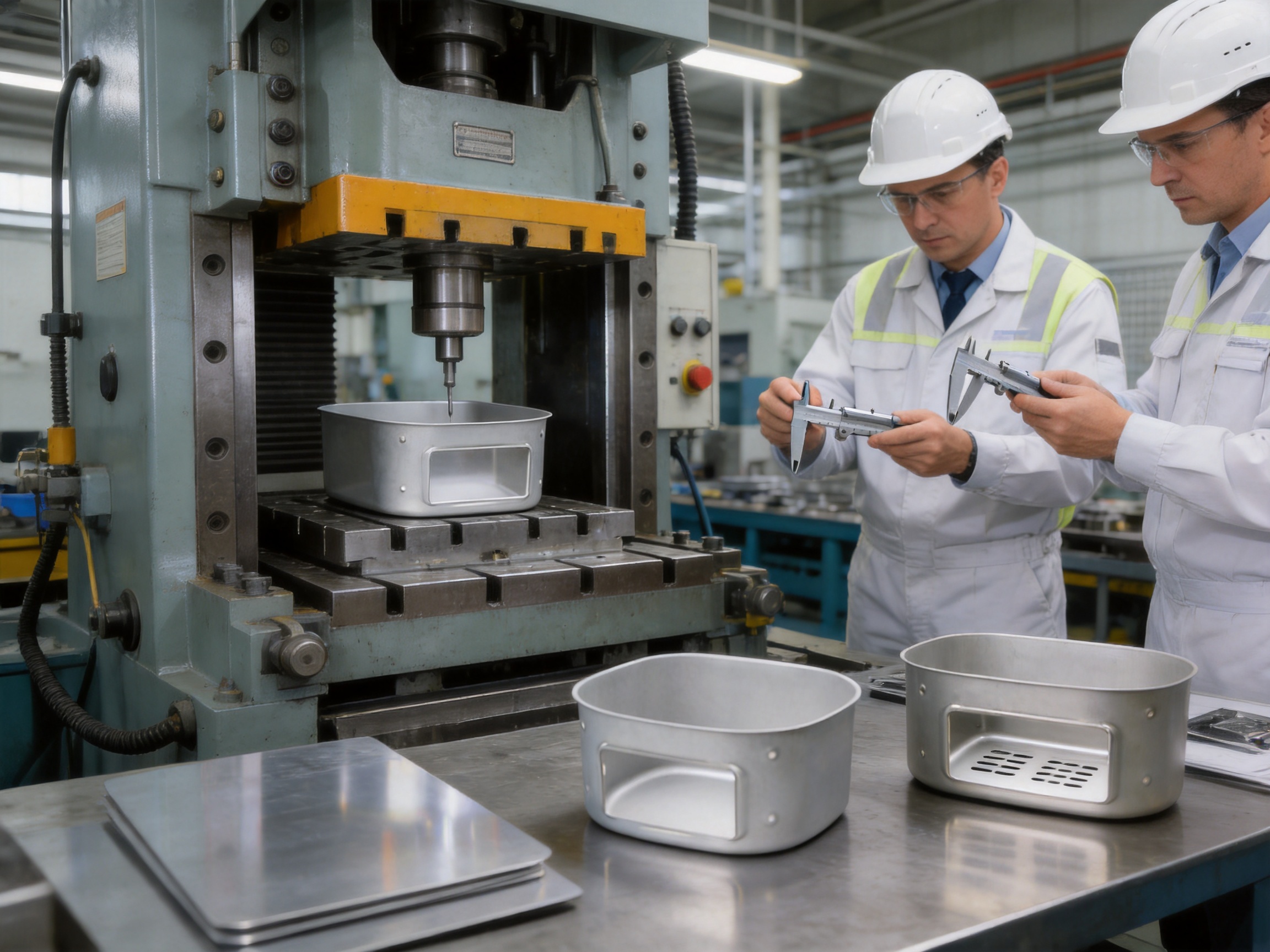
How to Develop a Custom Deep-Drawn Container
Step One: Define the Function
Begin by describing what the container must do. Identify whether it will hold, protect, drain, ventilate, support, shield, guide, or organize other components. Clarify whether it will be visible, exposed to cleaning, installed near heat, subjected to vibration, or handled frequently.
Step Two: Prepare Design Information
Provide two-dimensional drawings, three-dimensional models, sketches, samples, or photographs when available. Important dimensions include overall size, internal clearance, wall height, draw depth, flange size, corner radius, hole locations, slot dimensions, and mounting interfaces.
Step Three: Identify Material and Finish Requirements
State the preferred material and thickness if known. If the material has not yet been selected, provide the performance requirements so the manufacturer can recommend an appropriate option. Surface finish requirements should also be described, including appearance, texture, reflectivity, cleanability, and exposure conditions.
Step Four: Review Manufacturability
The manufacturer reviews the geometry and identifies potential risks related to drawing depth, material flow, cutout deformation, trimming, tolerances, and finishing. A design adjustment at this stage may improve production stability and reduce overall cost.
Step Five: Confirm Prototype and Tooling Strategy
For new products, a prototype can help verify physical fit and function. The tooling strategy is selected according to the required quantity, complexity, accuracy, and future production plan. A lower-volume program may use flexible tooling, while a larger program may justify dedicated high-efficiency tooling.
Step Six: Approve Samples and Begin Production
Before mass production, samples are inspected against the agreed drawings and specifications. The customer can confirm dimensions, cutout placement, finish, assembly fit, and appearance. Once the sample is approved, the production process can proceed with defined quality and delivery requirements.
Quality Considerations for Cutouts
Cutouts are functional features, not merely decorative openings. Their dimensions and locations can affect airflow, drainage, cable routing, fastening, safety, and the structural strength of the container. For that reason, they should be included in the initial engineering review.
Large openings near corners or edges may reduce local rigidity. Closely spaced holes may create a weak section if the remaining material is too narrow. Slots intended for wiring should be checked for cable clearance and edge safety. Drainage holes should be positioned to support complete liquid removal under the actual installation orientation.
Where openings are created after deep drawing, the manufacturer can select a cutting process that balances accuracy, productivity, and edge quality. Where openings are formed before drawing, the design team must consider how the material will stretch and move during forming. In both cases, inspection should verify the finished feature rather than relying solely on tool settings.
Surface Finish and Maintenance
The surface finish influences how the container looks, feels, and performs during maintenance. Brushed surfaces can provide a practical industrial appearance and may help mask minor handling marks. Polished surfaces offer a bright, smooth appearance but may require careful handling to maintain their visual quality.
Sandblasted finishes create a matte texture that can reduce reflectivity and provide a distinctive appearance. Electropolished surfaces can provide a smooth finish for applications where cleanability and surface quality are important. The selected finish should be evaluated together with the operating environment, cleaning agents, and handling procedures.
Regular maintenance should follow the requirements of the complete equipment. Cleaning methods must be compatible with the selected material and finish. Abrasive tools, aggressive chemicals, or unsuitable cleaning procedures may damage the surface even when the original container was correctly manufactured.
Cost and Production Efficiency
The total cost of a deep-drawn container includes material, tooling, forming, cutout operations, finishing, inspection, packaging, and logistics. The lowest unit price is not always the lowest total cost. A product that reduces assembly labor, eliminates extra brackets, improves installation speed, and lowers maintenance requirements may create greater value over its service life.
Deep drawing can become particularly efficient when the same design is produced repeatedly. Tooling expenses are distributed across the production quantity, while the repeatability of the process supports efficient inspection and assembly. For low-volume work, a suitable tooling strategy can help balance development cost with the need for customization.
Material utilization should also be considered. Blank dimensions, nesting arrangements, flange design, and cutout layout can affect scrap levels. Early engineering review can identify opportunities to use material more efficiently without compromising strength or function.
Packaging and Delivery Considerations
Finished containers should be packaged to protect surfaces, edges, cutouts, and formed corners during handling and transportation. The packaging approach may depend on the finish, component size, stacking capability, order quantity, and customer’s receiving process.
Parts with polished or electropolished surfaces may require additional protection against scratches and contact marks. Containers with delicate flanges or exposed cutout edges may need separators or formed supports. For repeat orders, returnable packaging or standardized carton arrangements may improve handling efficiency.
Delivery planning should account for tooling completion, prototype approval, production scheduling, finishing, inspection, and packaging. Clear communication of the required delivery date and forecast demand helps the manufacturer plan capacity and materials more effectively.
Frequently Asked Questions
What is the main advantage of a deep-drawn container with cutouts?
The main advantage is the combination of one-piece formed construction and customized openings. The container can provide strength, cleanability, and dimensional consistency while incorporating vents, drainage holes, wiring passages, mounting holes, or other features required by the application.
Can the container be made according to a customer drawing?
Yes. The product is designed for customization. Customers can provide drawings, three-dimensional models, samples, sketches, or functional requirements. Dimensions, cutout patterns, material thickness, corner details, surface finish, and packaging can be reviewed for production.
What thicknesses are available?
The general thickness range is approximately 0.5 to 3.0 millimeters. The appropriate thickness depends on the material, draw depth, dimensions, load conditions, cutout pattern, and required rigidity. A final recommendation should be confirmed during engineering review.
What types of cutouts can be produced?
Common options include round holes, rectangular openings, elongated slots, vents, drainage holes, mounting holes, cable passages, and custom profiles. The production method depends on the feature shape, tolerance, location, material, and order quantity.
Can the product be used in food-processing equipment?
Yes. Deep-drawn containers are suitable for many food-processing equipment designs because their one-piece construction and available smooth finishes can support cleanability. Material, finish, geometry, and cleaning requirements should be confirmed for the specific application.
Can the container be used in medical or laboratory equipment?
Yes. The product can be customized for housings, trays, covers, brackets, and internal equipment components. The final design should be reviewed according to the equipment’s cleaning, corrosion, dimensional, and environmental requirements.
Which surface finishes are available?
Available options include brushed, polished, sandblasted, and electropolished finishes. The best choice depends on the desired appearance, texture, cleanability, reflectivity, and operating environment.
Does deep drawing eliminate all secondary operations?
Not necessarily. Deep drawing forms the main body, but trimming, cutout production, deburring, additional bending, finishing, and inspection may still be required. The exact process route depends on the product design and the required level of precision.
Can Hongli support small orders?
Hongli supports flexible production requirements, including small-batch development and larger repeat orders. Customers should provide the expected quantity and future demand so the tooling and manufacturing strategy can be planned appropriately.
What information is needed for a quotation?
Useful quotation information includes drawings or samples, material preference, thickness, dimensions, cutout details, surface finish, annual or initial quantity, application, inspection requirements, and delivery target. More complete information generally allows a more accurate evaluation.
How does the company support OEM and ODM projects?
For OEM projects, Hongli can manufacture according to customer drawings and specifications. For ODM projects, the company can assist with process review, customization, prototyping, and conversion of a functional requirement into a manufacturable component.
Why is design review important before tooling?
Design review helps identify risks involving draw depth, material flow, wall thinning, wrinkling, cutout distortion, trimming, tolerances, and finishing. Addressing these issues before tooling can reduce development delays and improve repeat production.
Conclusion
The deep-drawn container with cutouts is a versatile solution for manufacturers that need a strong, clean, lightweight, and precisely formed metal component. Its one-piece construction reduces dependence on welded assemblies, while custom cutouts support ventilation, drainage, wiring, mounting, access, and integration requirements.
With thickness options from approximately 0.5 to 3.0 millimeters, multiple surface finishes, and flexible dimensional customization, the product can serve food-processing, medical, electronics, household appliance, automotive, and general mechanical applications. Its value extends beyond the individual component: a well-designed deep-drawn container can reduce part count, simplify assembly, improve appearance, support maintenance, and create more consistent production results.
Yuyao Hongli Optoelectronics Co., Ltd. combines deep-drawing and stamping experience with OEM/ODM customization, rapid prototyping, multiple workshops, quality control, and production support for both small and large orders. The company’s broad manufacturing background allows it to address projects involving deep-drawn parts, stamped parts, bending parts, kitchen appliance accessories, and automotive stamping parts.
For the best result, customers should involve the manufacturer early, provide complete design and application information, and review material, thickness, cutout geometry, tooling, surface finish, inspection, packaging, and delivery requirements as one integrated project. Through this cooperative approach, the deep-drawn container can be optimized for reliable performance and efficient long-term production.
References
1. Groover, M. P. Fundamentals of Modern Manufacturing: Materials, Processes, and Systems. Manufacturing process principles and sheet-metal forming considerations.
2. ASM International. ASM Handbook, Volume 14B: Metalworking—Sheet Forming. Technical guidance on deep drawing, material flow, tooling, and forming defects.
3. American Society of Mechanical Engineers. General engineering practices for dimensional control, manufacturing documentation, and inspection planning.
4. International Organization for Standardization. General principles for quality management and production process control.
5. Society of Automotive Engineers. Automotive manufacturing references concerning stamped components, repeatability, dimensional control, and production planning.
6. Manufacturing Engineering and Technology reference materials covering pressworking, tooling design, blank preparation, trimming, punching, and surface finishing.
Product: Deep-drawn container with cutouts
Previous Post
Deep-Drawn Rectangular Containers with Handles for Durable, Hygienic Storage
Next Post
High-Performance Air Fryer Containers for Efficient, Durable Cooking
News
-
-
What Is Deep Drawing Process and What Are Deep-Drawn Parts The deep drawing process is a sheet metal forming operation in which a flat meta...
READ MORE -
A flat mounting plate with three punched holes and a rectangular container with a fitted lid can come off presses in the same workshop, yet...
READ MORE -
Sheet metal bending is one of the most fundamental processes in metal fabrication. It turns a flat sheet of steel, aluminum, or copper into...
READ MORE
Get Fresh Updates Via Email
We promise we will never disclose your email address, and you can opt out at any time.
-
Quick Links
Home About Us Products Service News Contact Us -
Product list
Deep-drawn parts Stamped parts Bending parts Kitchen appliance accessories Automotive stamping parts -
About Us
Factory Honour FAQ -
News
Company News Industry News -
Contact Us
Address: South side of Shunke Road, Yangming Science and Technology Industrial Park, Yuyao City, Zhejiang Province, China Tel: +86-13905842349/+86-13738485724 Email: hongli@hl-stamping.com
Copyright © Yuyao Hongli Optoelectronics Co., Ltd. All Rights Reserved.
Custom Precision-Sheet/Sheet Metal Stamping Manufacturers
